Mirror grinding machine construction log
I started thinking about building my own mirror grinding
machine several years ago.
Having been on the ATM list now since almost the beginning of it here
on the web, I had
lots of of inspiration reading of others projects and viewing their
webpages
I started out
with wooden table and some bits cobbled out of our scrap bin at work,
I didn't
get to far and put it aside for a while as I built several med sized
dobsonian telescopes, A 15"
for myself and a 16" for the NBANB. Both of these mirrors were
bought, but I still wanted
to grind one myself. I ordered an 8" kit from Willman-Bell but it
has sat on the shelf for
several years
now.
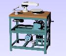
The current project really started out as a design exercise for my CAD
work, something to
hone my skills on. About the same time we scrapped a DoAll lapping
machine at work. Looking
over the interior of the machine I realized there was a treasure trove
of parts inside, ones ideally
suited to building a mirror grinder with. The machine contained
a large speed reducer (47-1 ratio),
a variable speed mechanism, motor mount and tachometer. the frame
was too small to be able
to fit the over-arm drive in so I left it. I started out copying
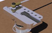
all of the existing parts into my CAD
program. I then sort of filled in the blanks.
Cad drawings
Construction pictures- all picture are linked to larger files, just
click on the picture to go to the larger image
All pictures taken with a Kodak
DC-290 digital camera at high res- 1900x1200 pixels
but have be reduced in size and
compression to speed download.
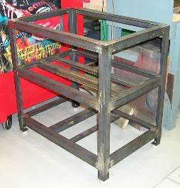
Basic frame after welding, 24w x 36l x 36h
constructed of 2 x 2 x 3/16 angle.
Various components for the mirror grinder.
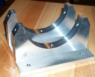 motor
cradle
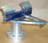 overarm
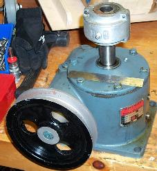 Speed reducer
Here are some pictures I took after assembling the platter drive
components (Feb
8, 2002)
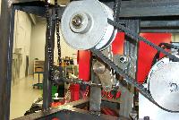
These photo's show the various pulleys and linkages that control the
variable speed drive

You can see the sprocket and chain drive that moves the pivoting mount
for the variable speed pulley
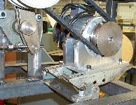
I spent a sunday afternoon at the shop machining the base for the
eccentric drive. Note the ruled markings on the side
to set the tool stroke. I still have to put on
the marked divisions. It would be nice to engrave them, but
I will probably
Just use number stamps.

I now have the frame painted and home in the basement.
The top has been glued up and the hole for the platter is in it.
I still have to drill the bolt holes for the platter and overarm as
well as the eccentric mounting area. I will coat the top
with fibreglas and epoxy resin to keep the water off of the MDF.
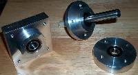
These pictures are of the intermediate
shaft bearing blocks for the speed reduction of the gearmotor
to run the overarm ,
and the bearings for the eccentric.
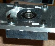
I have machined the bar that the bearing for the overarm reducers mount
to.
Its august now and I have started to assemble the components together
with only a few pieces left to make.
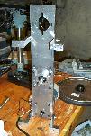
Here is the reducer frame with the gearmotor and intermediate bearing
assemble and the standoff
which will mount the unit to the bottom of the MDF top of the machine.
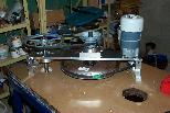
Here I have the pulleys mounted on the reducer frame and locating it to
drill the holes to screw it onto
the top.
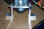
A closeup of the standoff brackets
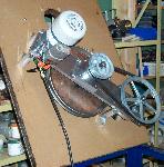
The reducer frame attached to the table top and ready to turn over and
bolt up to the table frame
Here are the clamps to possition the tool or mirror on the platter.
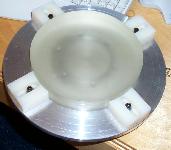
and the swivel mount to attach the mirror to the overarm
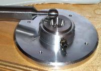
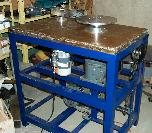
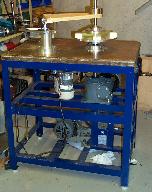
The grinder nearing completion, with all the parts inplace but not
hooked up yet.
The Speed Reducer still has to be aligned and the Variable Speed drive
must be aligned to the
pulley of the speed reducer.
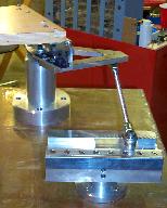
And a closup of the eccentric drive hooked up to the overarm
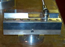
And a closeup of the eccentric itself.
I have the tachometer installed and the label plate for the speed
control
wheel attached.
The tach reads to direct rpm and indicates that my platter will rotate
from
6rpm up to aprox 60.
I had to install a weight on an extention attached to the motor mount
to
keep enough tension on the belts,
They are quite wide and thich and the weight of the motor alone was not
enough
to keep the belts from slipping.
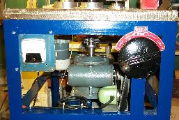
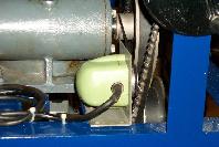
Here is a closeup of the tach motor. It runs from a rubber O-ring
around
the input to the speed reducer.
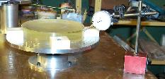
I placed the blanks on the platter to check the holding ability of
the
clamps I made up and used a magnetic base and indicator
to check the runout. It only took a min and I could get the blank
centered
within .004" and most of that was irregularitys in the
blank. I will mount a block of steel later to attach to magnetic
base
to.
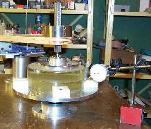
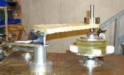
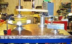
I
And some other views of the setup. The overarm is just resting
on
the blanks, nothing is glued or pitched together, just posed for the
pictures
:-)
Next step is to make a tile tool so I don't have to waste a
perfectly
good pyrex blank :-) and I have a dishpan that I have to modify
to
sit under the
platter to catch the grit and gunk. I have made up set of ply
forms
to match the mount under the platter and will heat the plastic pan and
press
it to shape.
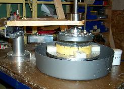
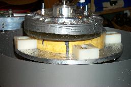
I finally got the drip tray made after a couple of tries. I found
a plastic tub the right diameter and then cut it down to the proper
height. I cut out a center hole
and used some of the remaining plastic to make a dam inside to keep the
sludge and water away from the center shaft and bearings.
I started grinding on the 22nd of July with an 8" pyrex blank from a
Willman-Bell kit I bought several years ago. I will start with an
f8 curve to start and see
how the machine works.
I also made a short animation of the grinding movement in AVI(1.7mb)
or as a animated GIF(2mb)
GRINDING LOG-----------------------------------------------------
July 22, 2003
Machine settings - Platter set at 15rpm - Overarm speed -
6 strokes per min (fixed), Stroke+/- 2.375"
aprox 10
lbs weight on
mirror. Started at 6:10pm using 60grit SiC.
Applied grit at aprox 5min intervals
using shaker
for grit and water in
spray bottle. Increased platter rpm to 23rpm and increased
weight
to 15lb
after 15min and ran for total of 1hr. This cleaned most of
the molded features off
of the blank
and gave me a
sagitta of .002" on the 3.5000" spherometer.
Ran 2 more 1 hour sesions with wets every
5min. Molded features all cleaned up. Sagitta to .004"
July 23, 2003
Increased weight to 15lbs, platter at 23 rpm, stroke at +/-
2.375" 60grit SiC
2 more sessions of 30min each. Sagitta
at .0058
July 24, 2003
Increased weight to 30lbs, platter at 23 rpm, stroke at
+/- 2.375" 60grit SiC
4 sessions for a total of 2hrs final sagitta
of .0119 or a ROC of 128.74"
Clean up-remove tool from platter and clean
all parts to all grit. removed tape from mirror and replaced
Started on 120grit SiC - Machine settings -
platter 31rpm, stroke 6rpm(fixed) Stroke +/- 2.0" 15lbs
weight.
2 session totalling 1hr.
Most of the pits from the 60grit gone. The outside 3/8" still a
bit rough. It will
probably take
another couple of hours to finish with the 120
grit. Sagitta increased slightly to .0124 or
a ROC
of
124"
July 25, 2003
Two more sessions of 30min with 120grit SiC, platter
31rpm, stroke 2.0" 10lb weight.
I applied some Dykem layout dye to the outer
1/2" of the mirror and a couple of bands across the mirror.
After the first 30min most of the Dykem was
gone but you can still see an area on the outer 1/4" with
some blue
specks. There are still a couple of pits but the
dykem was all gone after the hour of grinding.
Total of
2 hrs at
120grit so far.
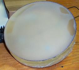
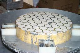
July 27, 2003
4 session of 30min with 120grit, platter 31rpm, Stroke
1.625, weight 30lbs. Sagitta increased to .013.
July 28, 2003
Stripped setup down, and switched to TOT.
Started on 220grit SiC. Platter 32rpm, stroke 1.25"
Weight 15lb
3 sessions of 30min, sagitta slowly coming
back, 0.0128". Switched to stationary overarm with
occasional
oscillation and switched from one side to the other at 5min
intervals
2 sessions of 45min, sagitta 0.0125
Mirror seems uniform so I switched to 320grit
SiC. 2 sessions of 30min Sagitta 0.0124
July 29, 2003
Cleaned up and washed down platter mirror and tool.
On closer examination found a half dozen pits.
Switched
back to
220grit.
2 sessions of 30 min, 220grit, platter 32rpm,
stroke 1.25, stationary overarm with occational oscillations. 15lb
weight.
July 30, 2003
Started on 320grit SiC. 2 sessions of 30
min, platter 32rpm, stroke 1.25, overarm stationary, weight 15lb.
Sagitta slowly
coming down to goal. Now at 0.01215". Very uniform
across mirror
July 31,2003
switched to 500grit SiC. Mixed grit with water
and drop of detergent in squirt bottle. Settles out very fast,
have to
shake to mix every couple of minutes. Platter 32rpm,
stroke 1.25. Overarm stationary. Weight 15lb.
3 sessions of 20min each. Sagitta now
at 0.01205"
Cleaned mirror, platter and tool, dried
mirror and check with low angle light. No Pits visible.
Very
uniform surface under 7 power loupe.
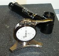
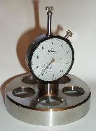
Aug 5, 2003
I was off to the Nova East Starparty for the
weekend, a
good turnout but lousy weather. We were rained
out for 3 days. :-(
Started on the 12micron grit today. Platter
32
rpm, 10lbs weight, alternating from one side to the other
of the
platter with 1.25"stroke. Leaving the tool at each side for 2-3
min
then switching sides.
One session
for 15min then Near Disaster
:-( The screws holding the tool to the pivot plate came loose
after I let it get
a little to dry. Luckily I got it stopped before any damage was
done. One of the main
causes was the lack of grooving as the
perifery of the
tool was ground down. I drilled out the holes
where the screws
had been and inserted some plastic wedges normally used in drywall and
used some
longer
screws. I then grooved out the tool to let the
grit and water circulate a little better. I removed
some of the outer
partial
tiles rather than have them fall out on the mirror. This also
made the tool easier to
remove from the
mirror
without having to slide the mirror to far to the side.
I started back on the 12micron grit doing another 2,
10min
sessions
Aug 6,2003
Did another 15min session with the
12micron
grit. Surface seems to very uniform with no pits I can find with
the
flashlight. Cleaned up and then switched to 5micron
grit. 2
session for total of 30min, same conditions
as previous.
Aug 7,2003
Finished up with the 5micron with another 30min
today.
Cleaned up the machine
Aug 11.2003
Started my
pitch lap today, what lovely stuff to work with :-) I have little
peices of pitch stuck all over the
place now. Its
even on
the body of my mouse here. I have an
extra blank so I used that for the pitch tool
instead of
making a new
dental plaster tool or using the existing tool (just in case) I
melted the pitch and
preheated the
blank in hot water. I wrapped
the blank with masking tape and then poured the
pitch
and got the mirror on before it cooled to much to form properly.
It didn't form conpletely so I dunked
it back in hot water
for a while
and hot
pressed to for a couple of hours. Then came the fun part,
grooving
the
tool. I tried the heated brass strip but it was too
slow. I used the slicing element on my Weller soldering
gun to melt
out the
grooves. Messy but effective. I used the soldering gun to
fill a couple of large
bubbles. Hot press the tool again and
left it overnight with
about 30lbs on it
Aug 12, 2003
Started in with the
CeO on the pitch lap. 32 rpm, 10lbs, 1.25 stroke,
Mirror on Top. Stationary overarm at
the stroke
limits.
Starting to get some vibration on the downward side of the
stroke. The drag on the
tool is
pushing toward the
overarm pivot on the downward side and
causing it to jump. So I am doing most of the
polishing on the up
side.
I did
3-10min sessions. The polishing seems to be going very
fast.
Aug 15, 2003
Cold press the lap
after last night with the netting in the Willman Bell kit.
Did another 10min today.
The drag is much
higher with a lot more vibration on the downward side of the
overarm. Finish is
getting
much better, only a slight
haze with the flashlight and even
then is hard to see unless
pointed toward you.
Left the mirror on
to cold press for the
night. Wrapped it with plastic to keep the water from drying out
and
make it easier
to get apart in the morning. (Didn't realy help that much)
Getting close to time to start testing,
contacted a friend
with a
foucault tester to borrow it. Hopefully this weekend.
Aug 16, 2003
Did 3 10min
sessions, cold pressed for the afternoon and did 2 more 10min
sessions. Center very clear now,
no spot with laser
in the
middle1/3.
Aug 18, 2003
Started and did 5min
but getting a lot of grabbing and the facets are getting really closed
in, I decide to recut
the lap, takes about
1-1/2 hours. Gawd what
messy crap this stuff is. So I cleaned it up and rebeveled the
lap edges as well
and brushed off
the debris. I soaked the lap in
hot water and then
hot pressed it for an hour.
Put the mesh in to
cold press for the
rest of the night.
Aug 19,2003
Polished for
2-20min sessions in the afternoon and then again in the evening for
3-20min sessions.
All but less than
1/2" of the outside is fully polished now.
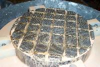
Aug 24, 2003
Did another hour of polishing in 3-20min
sessions. Mirror seems to be almost finished, maybe an 1/8"
of pits
showing up
with the laser pointer.
My buddy Garth Arsenault brought up
his tester and gave me a quick course in its use.
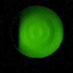
Aug 25, 2003 I was
a little dismayed at the first results of the foucault test. The
Ronchi test was even worse :-( Obviously
I had some severe zones developed by leaving the mirror at rest
to one side as the platter rotated. A little depressed I
set to work after the testing to repolish. I set the
machine to contiuous oscillation and polished for an hour
straight. I was
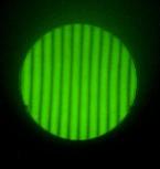
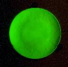
amazed when I put the mirror back up on the test stand and all
of the zones were gone. The foucault test was a uniform
green (from the LED) and the Ronchigram using a 50 lpi I
made on my laser printer appears to be almost perfect :-)
Sept 2, 2003
I havn't started the figuring yet. I have been cleaning the
basement and installing a new workbench I have built. I have
been doing a lot of research trying to determine the best
course of action in parabolizing the mirror. Presently stuck
between a subdiameter lap and a star lap, maybe I
will try both. I also want to build a tester for myself that will
allow
me to use my camera a little easier. The test
photo's above were taken with my Kodak DC 290 digital camera. It
was
a royal pain placing the camera at the right point of the
focus while bumping the tripod around to find it. :-) I am
drawing
up a tester to mount the camera and use a couple of suplus
micrometer heads I bought for just this purpose. I don't
like getting down and squinting, plus the fixed camera is
a more accurate, not relying on my head position and judgement.
Sept 4, 2003
I have started on the Foucault tester today. Here are some
cad drawings and some construction photos.
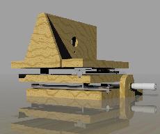
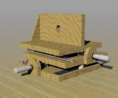
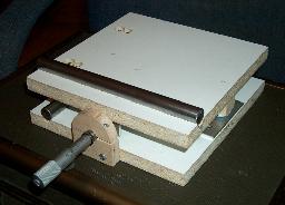
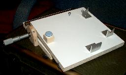
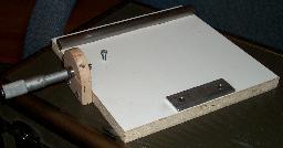
The tester is built from 5/8 melamine coated chipboard,
1/2" baltic birch ply, 1x1x1/8 alum angle, 5/8 ground steel rod
and some 1x1/8 alum flat bar. No machining involved
sofar, just a table saw, drill press and a bandsaw, but you could
get by with a hacksaw. The v-guides were cut and
then clamped together and filed to final shape to keep then as similar
as possible. The 5/8 bar was drill and tapped in the
center and is held in place with a 8-32 x 1/2 screw. The v-guides
are
also drill and tapped 8-32 and you can see the
countersunk
holes in the top board. The holes are slightly oversized to
allow for positioning of the y-guides to keep everything
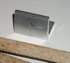
square. A furniture glide rests on the aluminum strip for the
third leg of the platform. In the middle right
picture is the anvil for the micrometer to push on. in the center
of the
position of the end of the micrometer is a carbide ball
left over from my 3.5" Spherometer. Without the ball bearing the
micrometer will grab the aluminum and try to lift
it. You can buy micrometer heads with a ball or radiused end, but
they
don't go for $9.99 at Princess
Auto :-) I bought the micrometers, disassembled them, sawed
off
the anvil portion and then
chucked it in a lathe and turned it round to be held by
the baltic birch clamps. A cheapy X-Y axis stage.
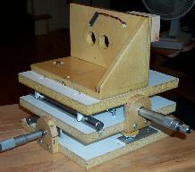
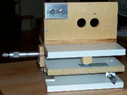
Sept 11, 2003
I have the Foucault test finished, several coats of
varnish and the LED wired in. I used a blue LED from Radio Shack.
Not wanting to be left without a battery while testing I
opted to use a 6v wall-wart from some battery powered tool of some type.
The blue LED is quite bright , plus I ground and polished
the end of the LED to reduce the spread of the light
source. I now
have to finish cleaning the basement of all the wood dust
from the project.
Sept 30, 2003
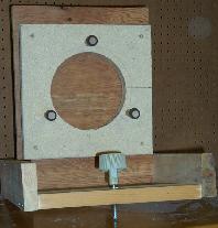
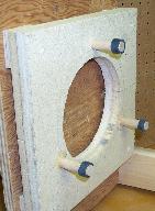
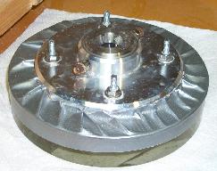
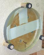
Finished up an adapter to use my buddies mirror holder for the Foucault
tester. I don't want to have to remove the mirror from
the adapter for the overarm linkage, so the adapter has a
hole in the middle to keep it off the back of the stand. I used
3-5/8"
hardwood dowels in a circle just slightly larger than the
mirror. I cut 3 sections of rubber hose that fits snugly over the
dowels
to act as retainers for the mirror. The lower 2
dowels are glued in and the top one is a snug fit that jams inplace and
then the
rubber hose is pushed into contact with the mirror to
prevent it from tipping forward. So with everything ready I can
start figuring
the mirror now.
Nov 14, 2003 Havn't done much on
the mirror in the last month, I have been busy with some other projects
and the mess in the basement
has
procluded andy serious mirror work. I did play with a star lap
but the results were not good. I hot pressed the lap with
a
plastic cutout to relieve the outer 1/3 of the lap with 8 triangular
sections. I should have cold pressed the lap afterward because
the
results were not to good. Back to full contact and then clean it
up back to a sphere.
This page updated Sept 31, 2003


 motor
cradle
  overarm
  Speed reducer


